
Construction of the Philips “All Purpose” projector DP70 |
Read more at
in70mm.com |
| Written by: Philips Cinema, a division of Philips Electro Acoustics division (ELA) in Eindhoven, Holland | Date: 11 June 2005 |
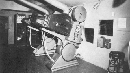 Typical
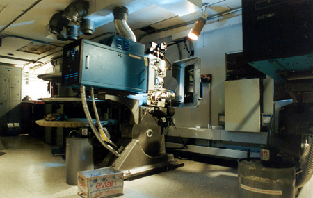
DP70 installation. Image by Philips. Typical
DP70 installation. Image by Philips.The successful demonstration of the Todd-A.O. system on the 15th of October 1954 concluded a long period of laborious research and experiments. At the beginning, normal 35mm projectors modified for the purpose were used for the experiments. Soon it was found, however, that these modified 35mm projectors - although usable for the experiments – were by no means suitable for normal use. The Cinema Department of the Philips works in Eindhoven (Netherlands) were therefore asked to develop a special projector which had to be suitable for running 70mm films with magnetic sound tracks and which after replacement of some easily removable parts could be made suitable rapidly for the reproduction of 35mm films with optical sound track and of CinemaScope films with four magnetic sound tracks. It will be obvious that for the projection of 70mm films the projector must satisfy special demands. |
More
in 70mm reading: DP70 - The Todd-AO Projector DP70 Story DP70 Cinemas everywhere DP70 Serial Numbers Todd-AO 70mm Projectors Construction of the Philips “All Purpose” projector DP70 (PDF) |
Driving Mechanism |
|
 Image
by Philips. Image
by Philips.For the projection of 70mm films the driving mechanism has to be much heavier than for normal 35mm films, since: 1. 70mm films have a much greater mass than 35mm films; not only are these films twice as wide but also the picture frames on 70mm films are higher: there are five perforations per frame instead of the usual four. 2. The speed of 70mm films is 30 frames/sec instead of 24 frames/sec. The driving mechanism of the Philips DP70 projector is housed in an oil-tight casing (Photo II), closed hermetically by means of a large cover, which protects it completely against dust. The cover is fixed with five screws only and can therefore easily be removed for inspection of the mechanism and simply be re-fitted. The driving mechanism itself is very sturdy and at the same time very simple thus perfectly reliable. Like in the well-known Philips FP7 projector, all the sprockets, the intermittent mechanism, the shutter and the take-up spool are driven by a sturdy vertical main shaft. In the DP70 projector this shaft is driven by a horizontal shaft, which also drives the spur-gear oil pump which is located at the bottom of the projector housing and hence is always below the oil level. All the gear-wheel transmissions and bearings, are abundantly lubricated via an oil conduit with tappings. The horizontal driving shaft is coupled directly to the driving motor for a speed of 30 frames/sec and it is coupled via a gear-wheel transmission to a second motor for a speed of 24 frames/sec. The use of separate synchronous motors greatly facilitates change-over from one speed to the other - simply by means of a selector switch - and it has the advantage over a speed-change gear box that the construction is simpler and therefore more reliable. Intermittent Mechanism The intermittent mechanism of a projector for 70mm films has a heavy task to fulfill. In principle, the intermittent mechanism of the DP70 projector equals that of normal 35mm mechanisms, but it is of much more robust construction. However, to keep the acceleration forces and therefore wear of the mechanism as low as possible, it is of the utmost importance that the Maltese cross and the intermittent sprocket are light. As the sprocket has to be longer and of greater diameter than a normal intermittent sprocket, it was not so easy to find a good solution for this problem. Aluminium was the most obvious material, since it is light in weight, but it is also soft and therefore not suitable for the manufacture of sprockets. After many experiments, a special method was found for hardening the surface of the aluminium and a life test proved that the thus treated aluminium sprockets could effectively stand comparison with chromium-nickel sprockets. Since aluminium has furthermore the great advantage that it is anti- magnetic, it was also used for the manufacture of the other sprockets. |
|
Picture Gate |
|
 Colosseum,
Oslo, 1995. Image by Thomas Hauerslev Colosseum,
Oslo, 1995. Image by Thomas HauerslevThe larger size of the picture frames entails also a different construction of the picture gate. The steadiness of the picture on the screen depends to a great extent on the way in which the film stops in the gate after the intermittent sprocket has moved it over the distance of one frame. Due to the greater weight of the film, the normal construction, (a flat runner plate and resilient pressure skates) is inadequate to obtain sufficient braking power. For a good definition it is furthermore necessary that the distance between the film in the gate and the projection lens does not vary. When a flat gate is used, 70mm film is liable to bend in a transverse direction and this cannot be remedied. For this reason the DP70 projector is equipped with a curved runner plate (Photo III). The slight bend in a longitudinal direction gives the film a greater stiffness in transverse direction. The concave side of the runner plate faces the lens. It is impossible to use normal pressure skates with a curved runner plate. The pressure skates have therefore been replaced by thin steel strips which are fixed to a hinged plate. The pressure in the gate can be adjusted by slightly tightening or slackening these strips. Apart from the smaller distance between the running faces of the plate and the smaller aperture, the construction for 35mm projection is just the same as that for 70mm projection (see Photo V). The hinged plate faces the shutter and has to be pushed aside for threading the film. This formed another problem for the designer, since the shutter is placed close behind the gate. This problem was successfully overcome by designing a construction in such a way that the knob for pushing aside the plate (Photo III, round knob at the left) can only be operated when the shutter is in such a position that the plate can pass freely, whilst it is furthermore impossible to start the projector when the plate is pushed aside. |
|
Shutter |
|
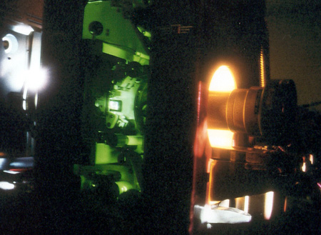
 DP70
prototype at Todd-AO Stage A in Hollywood, Califorrnia 1994. Image by Dan
Leimeter. DP70
prototype at Todd-AO Stage A in Hollywood, Califorrnia 1994. Image by Dan
Leimeter.The DP70 projector is equipped with a one-blade conical shutter with a very large diameter. At a film speed of 30 frames/sec the shutter rotates at a speed of 3600 r.p.m. and at a film speed of 24 frames/sec at a speed of 2800 r.p.m. This type of shutter has been chosen for the following reasons: The Todd-A.O. system is intended in the first place for the projection of very large pictures. Loss of light therefore must be avoided as much as possible. The large cross-section of the light beam (the image of the crater must cover the mask of 51 x 22 mm) makes it impossible to use a drum shutter which is eminently suitable for projection of normal films. The conical shutter can be mounted close behind the mask, so that it intercepts the light beam where it is narrowest. This in conjunction, with the large diameter and the high speed guarantees for this type of projector the smallest possible angle of interception and the highest efficiency. |
|
Cooling |
|
|
As the image area of the film can only be cooled by air, the shutter of the DP70 projector has been constructed as a powerful fan which sucks in the cold air from the rear of the projector and blows it against the film in the gate. |
|
Lens Holder |
|
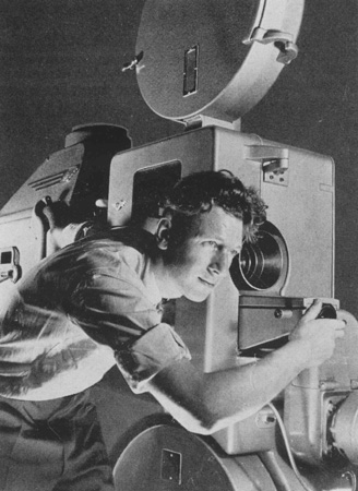
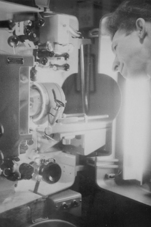 ABC Sheffield, England with Don Sykes operating the DP70 in 1964. Image by Don Sykes ABC Sheffield, England with Don Sykes operating the DP70 in 1964. Image by Don SykesThe Todd-A.O. system requires a very large optical system. The size of this system determines that of the lens holder. The lens is focused by means of the knob underneath the carriage (Photo I) over which the entire lens holder slides during focusing; this adjustment is free of any play. Special attention has been paid to the precision of this adjustment, since either a too fine or a too coarse adjustment may render focusing difficult. Sleeves with different inner diameter can be mounted into the lens holder to fit the lenses necessary for the different projection systems. For the projection of 35mm films the optical axis is shifted over the required distance by pushing the little knob in the slit of the lens holder over the whole length backwards through this slit. |
|
Sound Heads |
|
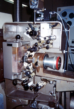
 Magnetic
soundhead for 70mm magnetic film. Image by Thomas Hauerslev Magnetic
soundhead for 70mm magnetic film. Image by Thomas HauerslevThe soundhead for scanning of magnetic sound tracks is located in the top part of the projector to the right. Either a scanning head for 70mm films or a scanning head for CinemaScope films can be placed on the two guide pins at the top bf the two rotating sound drums (Photo III) of anti-magnetic material. The two flywheels on the shafts of the sound drums are shown in Photo II (at the top to the left). The guide rollers of the sound-head and all other guide and pad rollers. which are in contact with the magnetic soundtracks are made of nylon. The sound-head forms one unit which can be removed after loosening four screws. The path of a normal film through the projector and the optical sound-head is shown in Photo IV. This sound head is located at the bottom to the left; it forms also one easily removable unit. One of the most important characteristics of this sound head is that in the scanning system a 13.5 time enlarged picture of the sound track is projected on to the scanning slit. This picture is visible through an observation window, so that the position of the sound track with respect to the slit can easily be adjusted by the projectionist. The same system is also used in the normal Philips projectors. |
|
Spool Boxes |
|
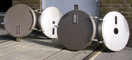 As the size of the film is larger and the film speed is higher than for
normal projection, the spool boxes of the DP70 projector are much larger
than the normal spool boxes; they are suitable for 950 m (3100 ft) of 70mm
film which corresponds to a projection time of 22 minutes. As the size of the film is larger and the film speed is higher than for
normal projection, the spool boxes of the DP70 projector are much larger
than the normal spool boxes; they are suitable for 950 m (3100 ft) of 70mm
film which corresponds to a projection time of 22 minutes.The spools are much heavier than the normal 35mm spools and therefore it was not possible to use the standard 3/8” spool shafts; the spool shafts of the DP70 projector have a diameter of ½”. Both spool boxes are provided with adjustable friction devices. The upper spool box is illuminated and equipped with time scales for the projection of both 70mm and 35mm films. The rollers in the firetraps have a large diameter so that even warped films are passed through without risk of damage. Light Source The shape of the projector and of the mounting table are such that any light source can be used, provided that its optical properties match the image size. |
|
Parts For Modifying The Projector |
|
 As, for the time being, it is not to be expected that a given theatre will
only show 70mm films, it is necessary that the projectors can also be made
suitable for running 35mm films. As, for the time being, it is not to be expected that a given theatre will
only show 70mm films, it is necessary that the projectors can also be made
suitable for running 35mm films.The DP70 projector is undoubtedly most universal in this respect: any actually known film system can be shown with this projector. The parts which have to be substituted or added for the projection of 35mm films are shown in Photo V. The modification takes only ten minutes. The mask of the gate for 35mm films can be replaced in a few seconds by that for CinemaScope films or by a wide-screen mask. All the sprockets used in this projector and the rollers of the first traps are universal and need not be replaced. Each sprocket is provided with two sets of teeth, one set spaced for 7Omm film and the other spaced for 35mm film which are located between the outer or 70mm set of teeth. The outer flanges of the intermittent sprocket have 20 teeth and the inner flanges 16 teeth; for the other sprockets the number of teeth is 30 and 24 respectively. The teeth have the required shape for CinemaScope film. The motors can be coupled in a simple way with an interlock motor for showing image films with separate sound film and for 3-D projection according to the twin-film system. |
|
Summarizing |
|
 Mann National Theatre Westwood,
California, USA. Image by Thomas Hauerslev 1994. Mann National Theatre Westwood,
California, USA. Image by Thomas Hauerslev 1994.Summarizing it can be said that the DP70 projector is suitable for: |
|
|
Go: back
- top - news index Updated 21-01-24 |