
Dimension 150 Visual Display for U.C.L.A. Driving Simulator |
This article first appeared in |
| Written by: S. F. Hulbert and C. K. Wojcik. Institute of Transportation and Traffic Engineering University of California, Los Angeles. Document supplied to "..in 70mm - The 70mm Newsletter by Dr. Richard Vetter | Issue 49 - June 1997 |
 Richard
Vetter and Carl Williams Richard
Vetter and Carl WilliamsVisual display is the key to successful simulation and has been the subject of many intensive investigations. In the driving simulator it is desirable to present all of the normal visual environment to the driver - an unprogrammed display on a hemispherical screen in full color, fine detail, brightness, and stereoscopic vision. Unfortunately, the present state of the art in this field is still far from this goal. The following is a brief review of the most suitable techniques. Of all the methods, motion picture techniques have the best optical characteristics but they can only produce a programmed display. A number of commercially available, wide-angle, motion picture systems produce a scene large enough to fill the entire field of view of the driver as he looks through the front windshield. The better known systems are Cinerama, Cinemiracle, CinemaScope, Circlerama, Dimension 150, Todd-AO, and Jam Handy. Both Cinerama and Cinemiracle are three-projector systems with a total field of vision of 146 deg. Circlerama uses 11 projectors and 11 screens to form a 360 deg field of vision. CinemaScope, Todd-AO and Dimension 150 are single-projector systems and their field of vision are 114, 128 and 150 to 180 deg, respectively. The Jam Handy system is also a single-projector system that uses anamorphic lenses and is used in conjunction with a spherical screen, and its field of vision is 180 deg horizontal and 90 deg vertical. In wide-angle pictures it is desirable to have the same amount of pictorial information per unit area as in a smaller angle picture and the same level of brightness, since the purpose of making a larger picture is not to have it viewed from a greater distance, but rather to enlarge the visual environment of the observer. For these reasons wide-angle, single-projector systems, use larger films and more powerful projection lamps. To improve further the brightness of the picture, special high-gain screens are employed. Expected resolving power of good quality films is 50-100 lines/mm, which for 70mm film and 140 deg field of vision can produce on the screen a picture with resolution of 2-3 minutes of arc. High-gain curved screens always involve losses in image quality due to cross-illumination. The best solution to this problem is the D-150 screen. Use of stereoscopic pictures in driving simulation is possible. However, one can expect a number of problems in application of this technique. At the present state of the art, stereoscopic pictures have a narrow field of vision, and in applying the existing stereoscopic picture techniques to wide-angle projection systems, great difficulties can be anticipated in matching the images. Since the viewer is required to wear two normally polarized lenses, a certain amount of realism would be taken away. Also the presence of the curved windshield between the viewer and the screen is quite likely to cause cross-polarization of the picture and thus greatly reduce its quality. A high-fidelity driving simulator must allow the driver to make free selection of velocity and position. It is reasonably easy to vary the speed of the projector within certain limits. The lower limit is dictated by a phenomenon called flicker. Film rate must be 16 frames per second or greater to avoid flicker. The upper limit is imposed by the tensile strength of the film. Motion picture displays have no potential for varying the speeds of other vehicles relative to that of the simulated vehicle. This is a very serious shortcoming and there are no satisfactory ways of solving this problem. Conventional motion pictures show only a scene from the view-point of the camera position. This makes it impossible for the driver, for example, to change lanes. By rotating the projector about its vertical axis it is possible to make the shift along the screen to the left or to the right. To the driver this action results in a rotation of the vehicle with respect to the road. Since the path of travel has not been changed by this action the overall impression of the driver is that he is skidding. To simulate a lane change one has to take two films synchronized, one for each lane and project them simultaneously from two adjacent projectors. While the scene from one of the projectors is displayed on the screen the scene from the other projector is masked out. Changing lanes in such a case amounts to switching the scenes from one projector to another. Unfortunately this change of scenes produces a noticeable jump from one lane into another. To diminish this type of discontinuity in visual display one have to increase the number of cameras and projectors so the lane change is taken in a number of small steps instead of one large jump. In spite of these limitations the motion picture technique has to be considered as the best method of visual display for certain types of studies in which the driver is restricted to a specific path as, for example, in a ride along a mountain road. This is so because other characteristics of motion pictures, such as resolution, brightness, size of field of vision, and color are superior to those of other techniques in terms of making the visual display realistic. |
Further in 70mm reading: |
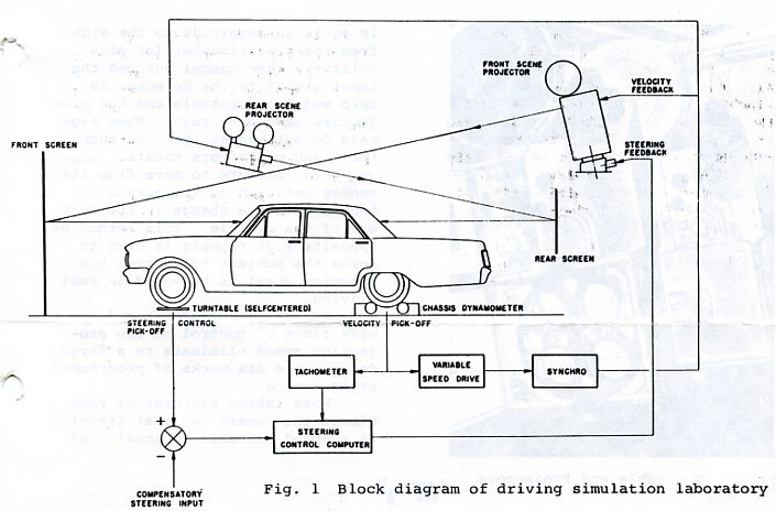 Fig.
1. Block diagram of driving simulation laboratory. The U.C.L.A. Driving Simulator.
Press image to see enlargement Fig.
1. Block diagram of driving simulation laboratory. The U.C.L.A. Driving Simulator.
Press image to see enlargementThe U.C.L.A. Driving Simulator has been developed as a research tool in the field of highway safety (Ref.1). The block diagram of this facility is shown in Fig. 1. This simulator is a projection room in which an automobile is driven on steel rollers of a standard chassis dynamometer while the driver views the road scene that is projected onto a curved screen 8.5 ft in radius. The driver also views the road scene behind him by looking through the rear-view mirror at a motion picture projected on a screen placed beyond the rear window of the vehicle. The field of vision of the front view is 150 deg. The projection technique used is a special type of motion picture presentation called Dimension 150, in use under contract with Dimension 150, Inc. |
|
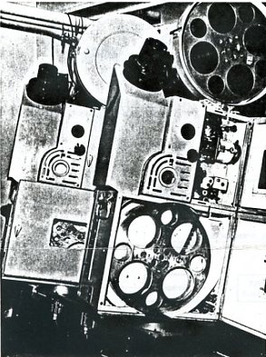 Fig.
2 Turntable and projectors. The U.C.L.A. Driving Simulator. Fig.
2 Turntable and projectors. The U.C.L.A. Driving Simulator. There are two variable speed projectors mounted on a turntable in the projection booth (see Fig. 2.). The projectors are manufactured by DeVry, Model MDX-35, modified for selsyn control, and their capacity was increased to 3000 ft of film. This length of film constitutes an average of about 30 minutes of projection time depending on the speed the driver chooses to drive. Since there are two projectors, one can be reloaded while the other is in operation. Hence, the only limitation on time of projection comes from the total length of film (number of reels). Film used for the front-view projection is 35mm colored film. The rear-view projectors are Dumont 16mm, continuous-image projectors, custom built and modified for selsyn control. They are mounted on a fixed base. The speed of the projectors is governed by the speed of the vehicle placed on the chassis dynamometer. To be more specific, one of the steel rollers of the chassis dynamometer drives two synchrogenerators which are interlocked electrically with syncro-motors of the projectors. One of the synchro-generators is interlocked with two synchromotors of the projectors in the projector booth; the second synchro-generator is interlocked with two rear-view projectors. The front view projectors in the projection booth are mounted on turntables which are driven by a dc motor. The voltage input signal to this motor is a product of two voltages; one representing the velocity of the car and taken directly from the tachometer of the chassis dynamometer and the second representing the rotation of the front tires of the vehicle. The latter is measured by resting the front tires on two turn plates that are spring-loaded to simulate the resistance present when making a turn. One of the turn plates is geared to a potentiometer. The voltage signal is proportional to the displacement of this potentiometer. |
|
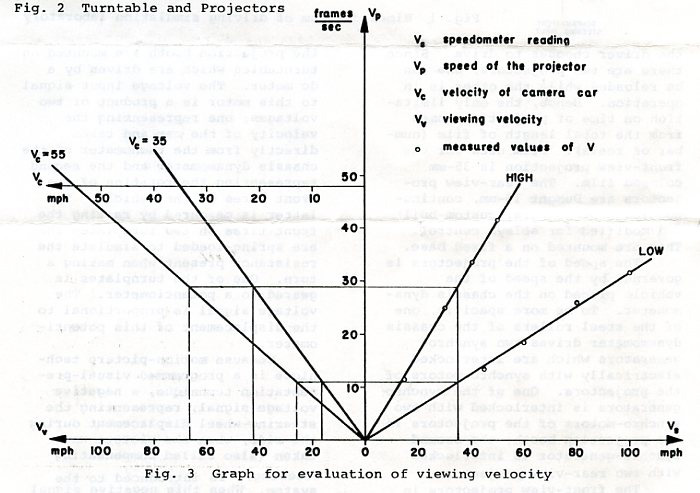 Fig
3. Graph for evaluation of viewing velocity. The U.C.L.A. Driving Simulator. Press image to see enlargement Fig
3. Graph for evaluation of viewing velocity. The U.C.L.A. Driving Simulator. Press image to see enlargementBecause motion-picture is a programmed visual presentation technique, a negative voltage signal, representing the steering-wheel displacement during the ride, when the picture was taken (also called compensating steering), is introduced to the system. When this negative signal is equal in magnitude to the signal from the potentiometer (of plus polarity) they cancel out and the input signal to the dc motor is zero and the turntable and the projector remain at rest. When signals do not cancel out, the turntable and projector rotate, causing the picture to move from its center position on the screen and thus simulate a change in the head-way of the vehicle. This method of opposite sign signals is used to force the subject to control the steering wheel as he would in real driving. The heading feedback and the wide range of control of the projection speed eliminate to a large degree, the drawbacks of programmed presentation. When taking pictures of road scenes the camera car must travel at a speed suitable to local traffic conditions, for example 35 mph on a two-lane road and 55 mph on a freeway. The speed of the camera is 24 frames per second and remains constant for all types of driving. Hence the number of frames per unit of distance varies. At 35 mph, the vehicle moves 2.14 ft per frame, i.e., a picture is taken every 2.14 ft; for 55 mph this value is 3.36 ft. Had two films been made these two different speeds and shown, at the simulated speed of the vehicle, say 35 mph, the driver would get an impression of going 35 mph when viewing the picture taken at 35 mph, but when viewing the picture taken at 55 mph he would get an impression of going 55 mph which certainly would be in conflict with the speedometer reading of 35 mph. To eliminate this problem a Vari-Drive unit was installed between the roller of the chassis dynamometer and the synchro-generator. The range of the reduction ratio of this Vari-Drive is 1:2.64. A nomograph for evaluation of viewing velocity is shown in Fig. 3. |
|
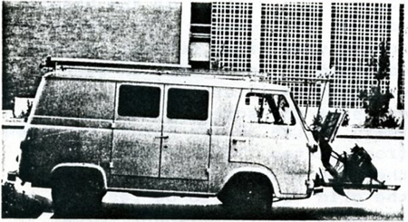 Fig
4. Camera car for filming road scenes Fig
4. Camera car for filming road scenesThe motion picture technique used in the U.C.L.A. Driving Simulator is a technique called Dimension-150. (Ref. 2). The Dimension-150 photographic system utilizes a conventional motion picture camera and a retrofocus lens. In addition, an afocal attachment, consisting of a conical anamorphosing mirror (see Figs. 4 and 5), and supplementary special cylindrical lens for negating astigmatism and reducing chromatic aberration. The function of the mirror is to receive a wide field of view compressed laterally at a ratio of 2:1. The camera, equipped with a wide angle prime lens, photographs this compressed image. The compression ratio of 2:1 has been selected, here, so that a standard anamorphic projection lens could be used for exhibition of the image. The shape of the mirror and the manner of which the optical axis of the camera is oriented to it are, of course, of great importance. |
|
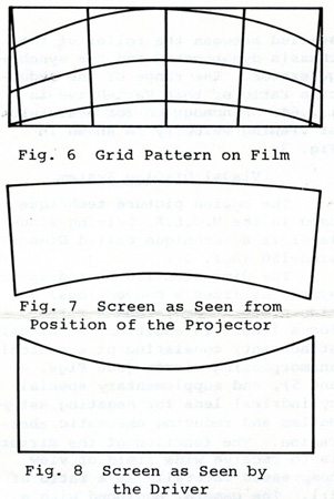 Fig
6, 7 and 8 Fig
6, 7 and 8Three types of precalculated distortions are present on the film image: lateral compression, negative keystoning of vertical imagery, and positive horizon curvature. All these distortions are canceled by the compensation distortions introduced in exhibition through the use of an anamorphopic lens, the oblique projection angle, and a deeply curved wide-angle screen. Fig. 6 illustrates a rectangular grid pattern in the real world, as it would appear on the film photographed using Dimension-150 technique. For the sake of clarity, the frame shown there is de-anamorphosed at the ratio 2:1. The vertical lines keystone and the horizontal lines curve toward the top of the frame. The radii of curvature increase slightly in the downward direction. In the Driving Simulator the outline of the curved screen, appears as seen in Fig. 7, when viewed from the location of the projector, or along the projection axis. The vertical edges keystone slightly, converging at the bottom; the bottom edge of the screen curves deeply inward, while there is little or no apparent curvature at the top. The screen outline appears quite different when it is viewed from the drivers´s point of view, i.e. along the mean viewing axis. The bottom edge of the screen appears to be straight while the top edge has definite apparent sag (Fig. 8). When the expanded (de-anamorphosed) film frame is projected onto the screen and viewed along the projection axis (Fig. 9), the vertical gridlines align with the vertical edges of the screen, although the keystone effect is evident. Note that the lowermost horizontal grid line follows the contour of the bottom edge of the screen. The top horizontal grid line, however, curves downward on both sides in such a way that is intersects the vertical edges of the screen at about one third of the screen height measured from the top. When viewed along the mean viewing axis (Fig. 10), the grid is seen to be restored to its original rectilinear format. The outer vertical grid lines align with the vertical edges of the screen, the bottom horizontal grid line follows the base of the screen, the uppermost grid line touches the top edge of the screen in the middle and intersects the vertical edges of the screen at a distance slightly less than one third of the screen height measured from the top. Thus, the distortions introduced in projection cancel one another. |
|
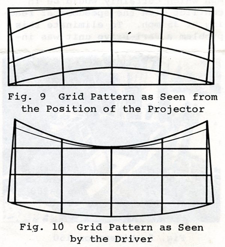 Fig
9 and 10 Fig
9 and 10The aspect ratio of the projected image in the Driving Simulator is 3:1. This aspect ratio is attained with a standard anamorphic lens of "two times" anamorphosing power. Because in this process the image is laterally compressed, there is no loss of visual information as it is in the case when spherical optics are used for exhibiting the image of the same aspect ratio 3:1. The camera used for taking pictures of the road scenes is a conventional Mitchell VistaVision camera (shown in Fig. 5). The film used in the camera is standard 35mm film; however, it is transported horizontally and the image is double the regular size (i.e. two regular frames are used for one image). Later, in the printing process, the images are reduced to size of the single regular frame (wide aperture print) on 35mm film in a conventional arrangement for vertical transport of the film. |
|
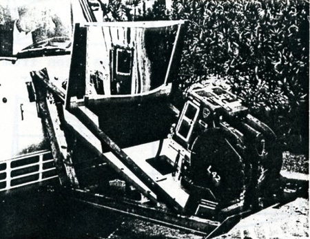 Fig
5 Dimension-150 Camera System Fig
5 Dimension-150 Camera SystemThe mirror, also shown in Fig. 5, is made out of polycarbonate clear plastic for greater flexibility and ease in forming a proper conical surface. For better optical performance it is the front surface that is silvered. (Hence, it is called a front surface mirror). The projection screen used in the U.C.L.A. Driving Simulator is high-gain screen developed by Dimension-150. It is a very directional screen that returns most of the light to the single viewer and in this way eliminates, for any practical purpose, the problem of cross-illumination so characteristic to all deeply curved screens. It is important to underline that the Dimension-150 process used in the U.C.L.A. Driving Simulator differs significantly from the Dimension-150 process used in the motion picture industry (Ref. 3). |
|
Conclusions |
|
|
The inherent shortcomings of motion picture displays for driving simulations have been partially offset by the development of the U.C.L.A. facility and the D-150 process. Further work is currently underway at UCLA to offset some of the remaining shortcomings. Three techniques are being developed for superimposing separately projected images on to the wide screen motion picture. A 16mm projector with a 3:1 zoom lens, driven
synchronously with the large scene projectors has been used to project an image only of the road surface and other vehicles ahead of the driver in the simulator. The brightness of this superimposed image and bleed through is coped with by using a mat to cast an appropriate shaped shadow on the screen onto which the superimposed image is projected. The zoom lens provides the capability of recapturing the dynamic interaction between the driver and other vehicles ahead of him. A similar approach is being used with a closed circuit projection TV system and model roadway to provide a realistic ability to change lanes as well as interact with other vehicles. A third system is proposed that would use a random access, rapid pull down film strip or slide projector with a zoom lens to again superimpose images of vehicles and to cause their signal lights to operate in dynamic interaction with driver of the simulator. |
|
| Go: back
- top - back issues Updated 21-01-24 |