
Todd-AO Equipment Catalog, Distortion Correction
Printer, Mark III |
Read more at in70mm.com The 70mm Newsletter |
| Captions by: Brian O'Brien, Jr. around 1997. Images by: American Optical Company, around 1955. | Date: 21.05.2014 |
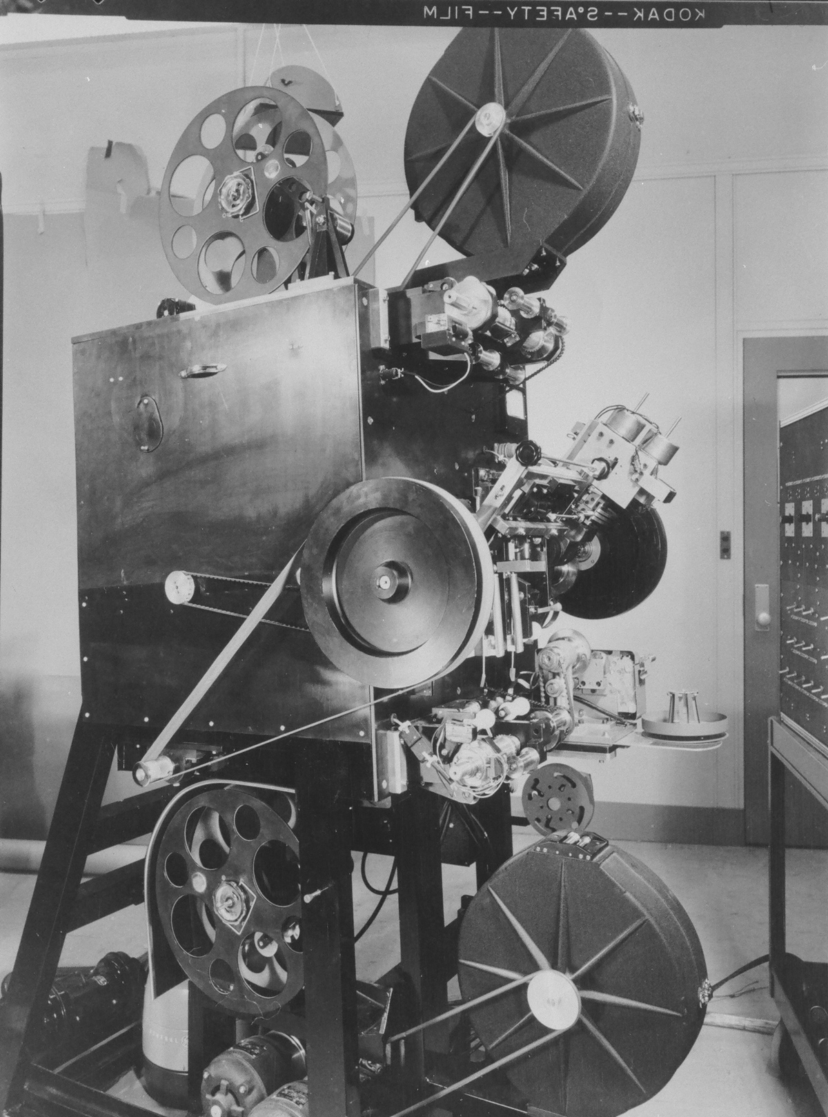
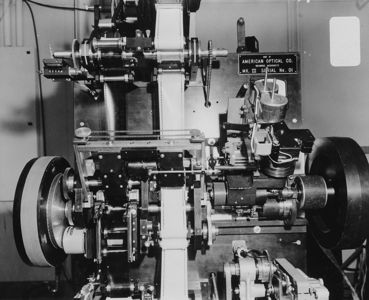
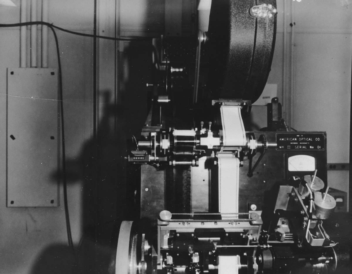
 Front
view of Todd-AO's Distortion Correcting Printer, Mark III installed in Fort
Lee, New Jersey Front
view of Todd-AO's Distortion Correcting Printer, Mark III installed in Fort
Lee, New JerseyThe Distortion Correcting Printing Process was initially meant to be an integrated part of the Todd-AO system. It was originally designed to eliminate three types of distortion, keystone distortion, distortion resulting from using a deeply- curved screen, plus correcting the distortion arising from use of the extremely wide-angle lenses, in both photography and projection. Grant Lobban Description of Todd-AO Mark III Printer Principle "Oklahoma!" Printing Operation in the Todd-AO Mark III Printer Todd-AO - Distortion Correcting Printing Process |
More in 70mm reading: Back to Todd-AO Catalog • Todd-AO Birth date • How Todd-AO Began • Todd-AO Home • DP70 / Universal 70-35 / Norelco AAII - The Todd-AO Projector • Description of Todd-AO Mark III Printer Principle • "Oklahoma!" Printing Operation in the Todd-AO Mark III Printer • Todd-AO - Distortion Correcting Printing Process Internet link: |
 Rear view showing control cables. Rear view showing control cables. |
|
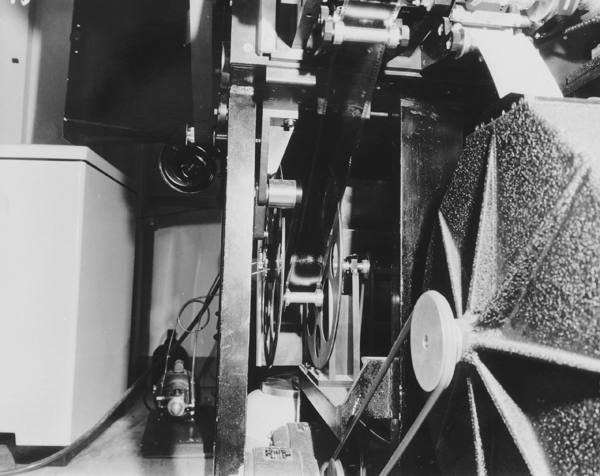
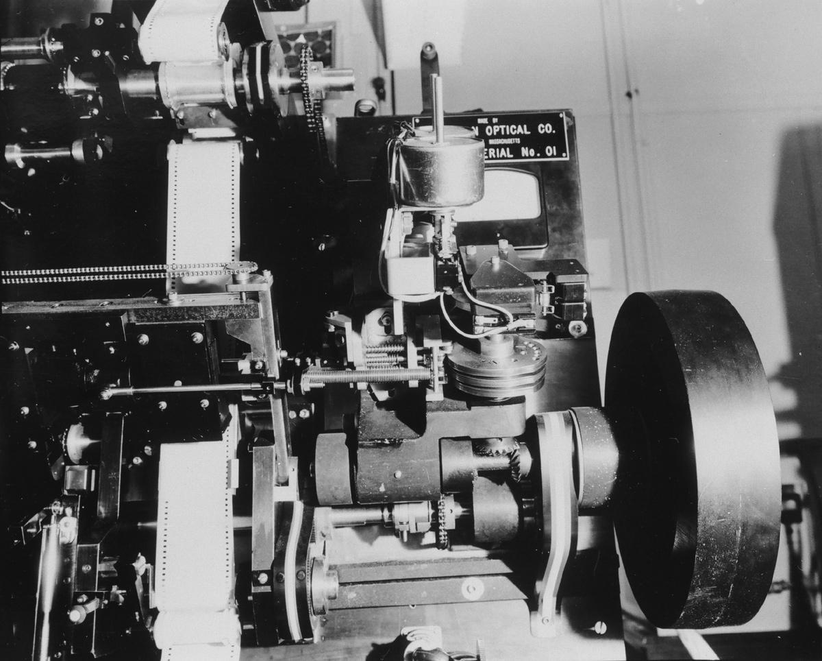
 Side view showing the supply reels at the top and the take-up reels at
the bottom. The closed reels are for the raw stock and the open reels are
for the negative. The circular pulley in the center is the heavy flywheel on
the printing drive to insure smooth motion. Side view showing the supply reels at the top and the take-up reels at
the bottom. The closed reels are for the raw stock and the open reels are
for the negative. The circular pulley in the center is the heavy flywheel on
the printing drive to insure smooth motion. |
|
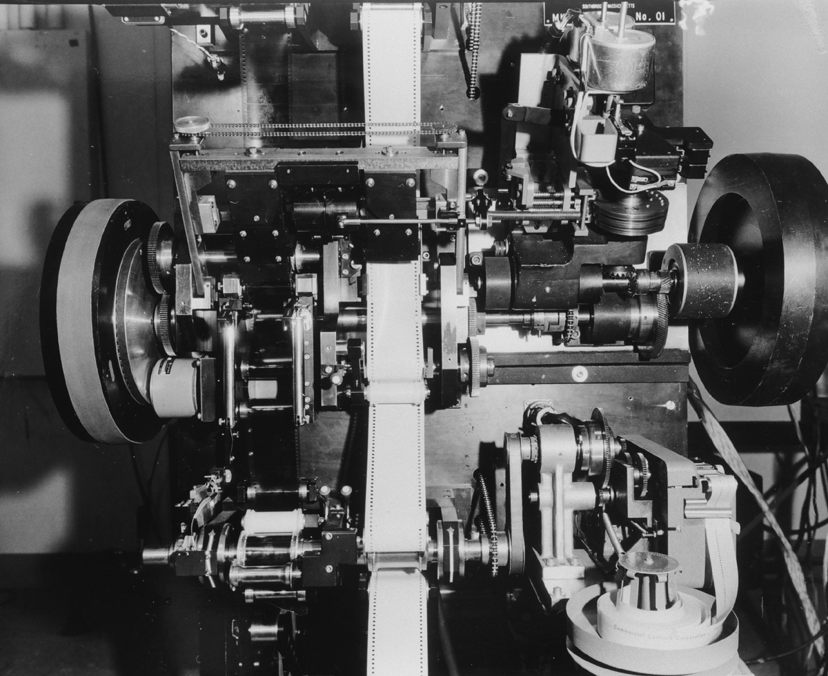
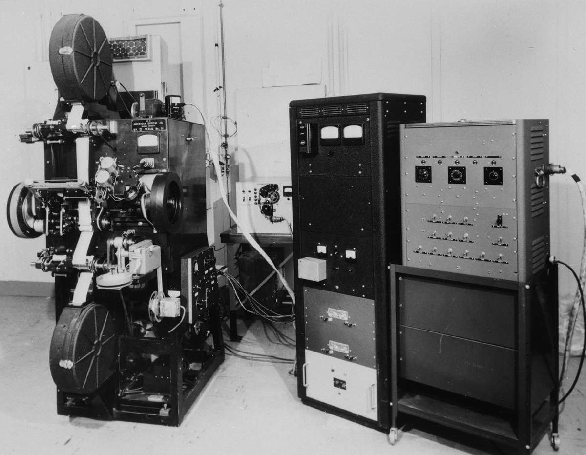 Long shot of printer and control boxes. Long shot of printer and control boxes. |
|
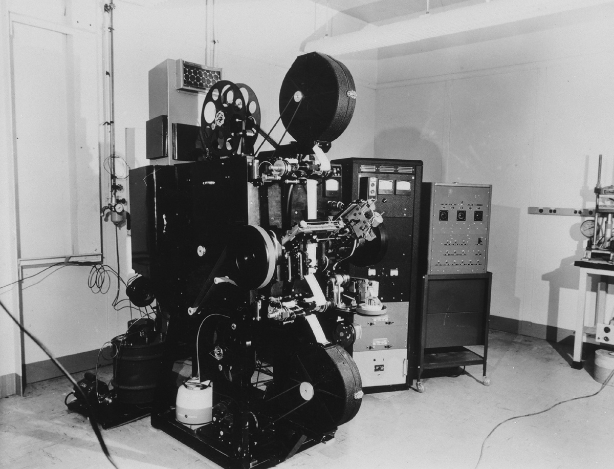 Long shot of printer with control boxes. Long shot of printer with control boxes. |
|
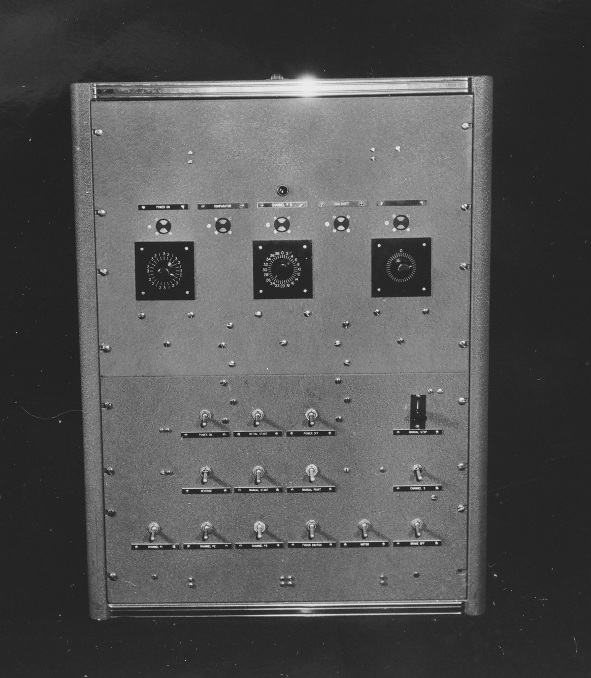
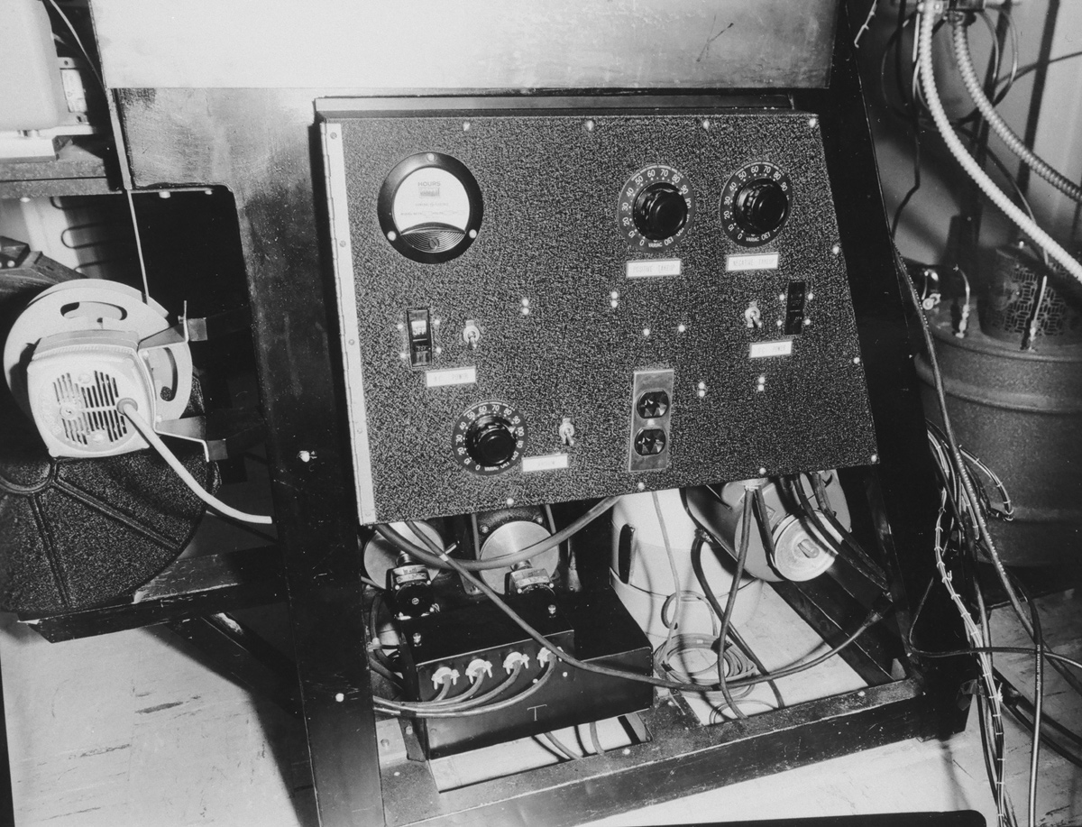
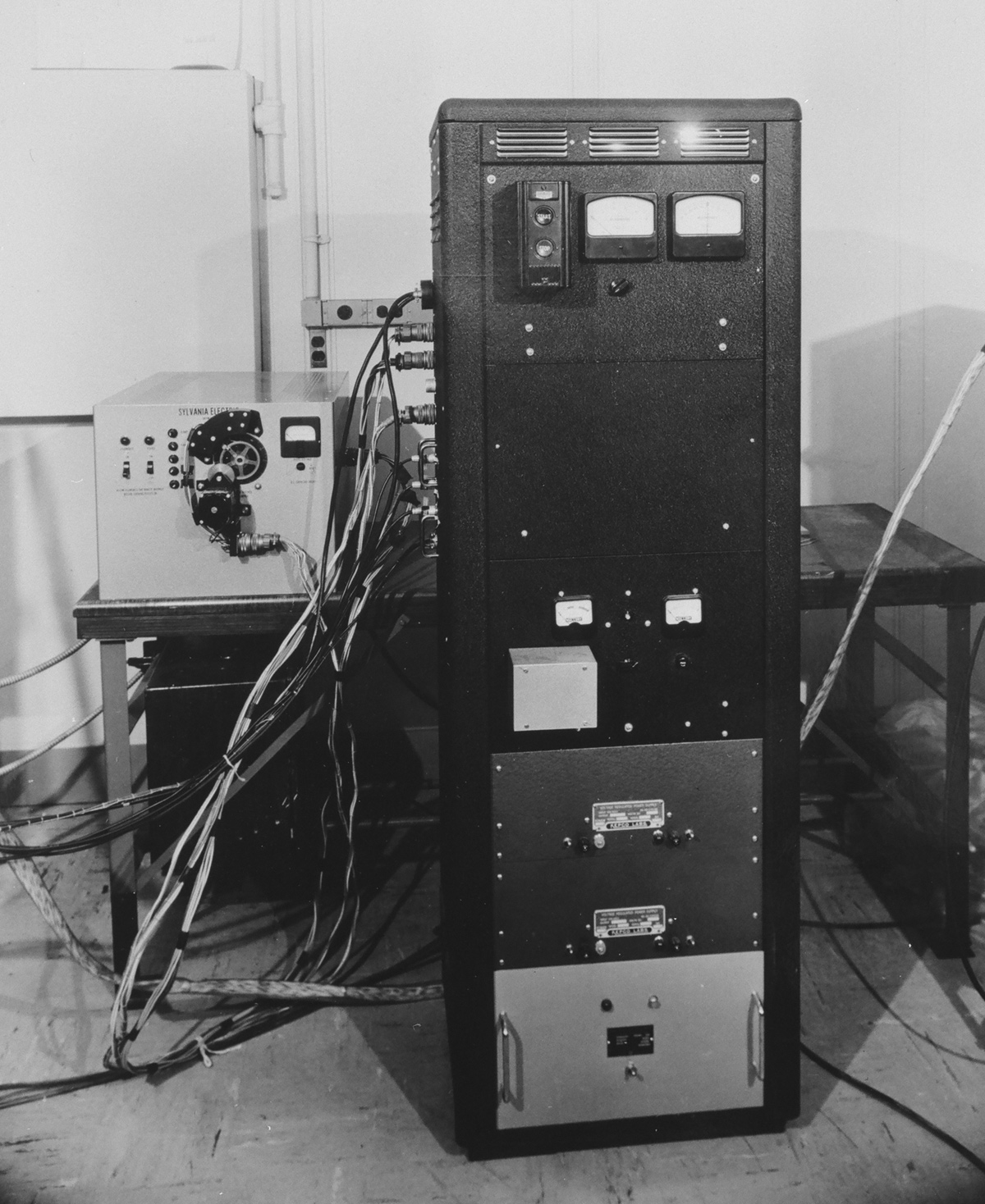 System control panel. System control panel. |
|
 Front of control cabinet Front of control cabinet |
|
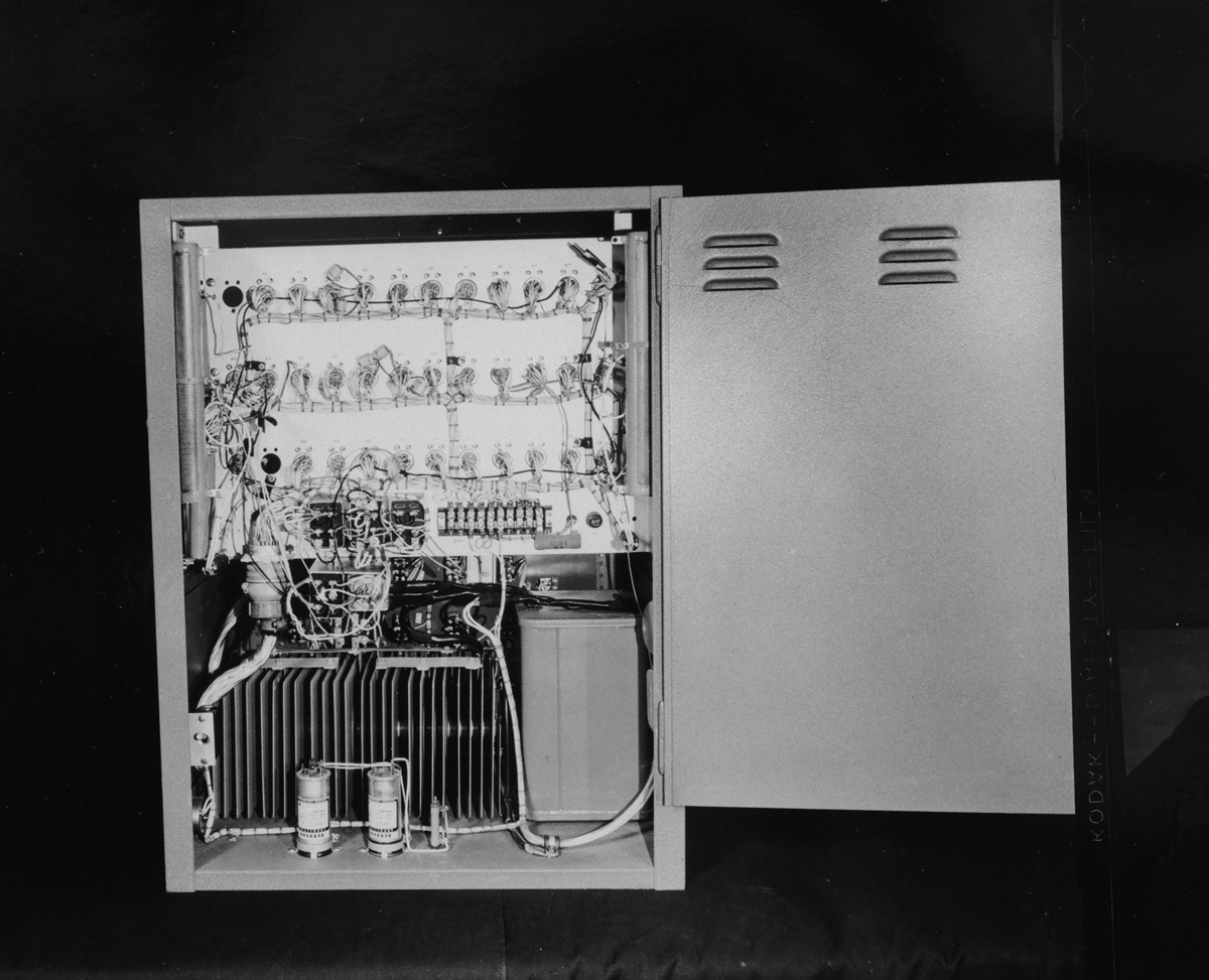 Inside control cabinet. Inside control cabinet. |
|
Film Path & Raw stock supply spool |
|
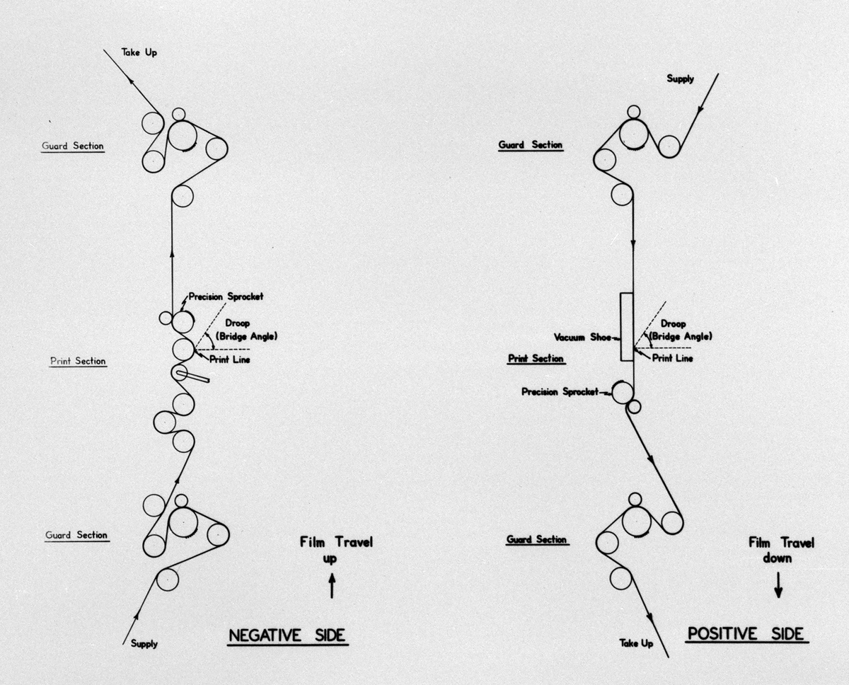 Diagram of the film path. Diagram of the film path. |
|
 Benny Grinsewitz
loading raw stock. Benny Grinsewitz
loading raw stock. |
|
 Raw stock supply spool with door open. Raw stock supply spool with door open. |
|
 Close-up of the take-up section with raw stock can on right and with
negative threading back to the open reel farther back. Close-up of the take-up section with raw stock can on right and with
negative threading back to the open reel farther back. |
|
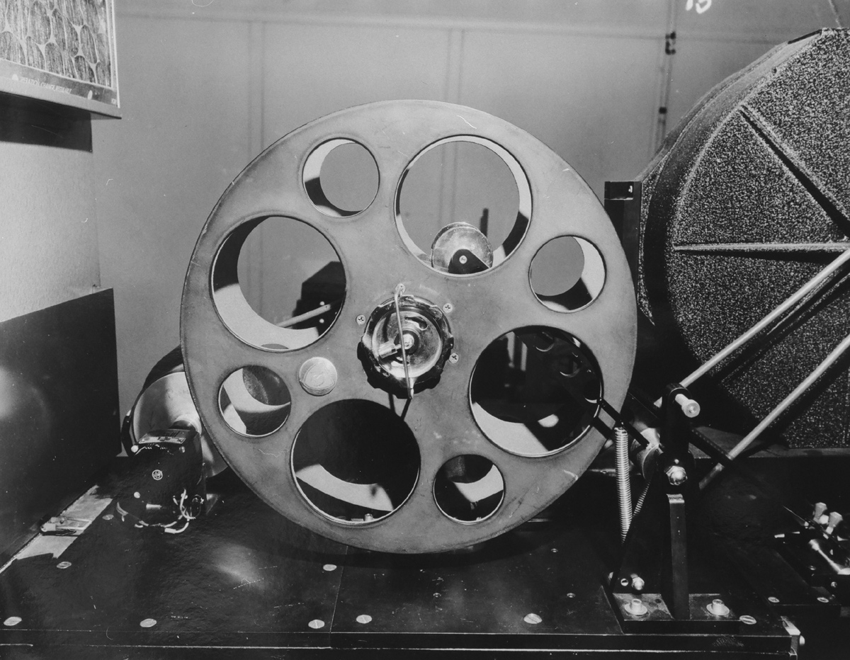 Negative and raw stock reels. Negative and raw stock reels.Supply section. |
|
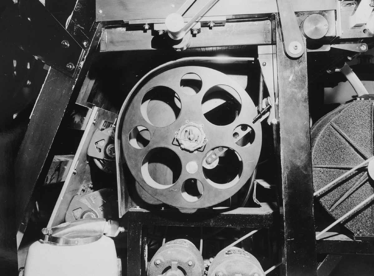 Negative and raw stock take-up section. Negative and raw stock take-up section. |
|
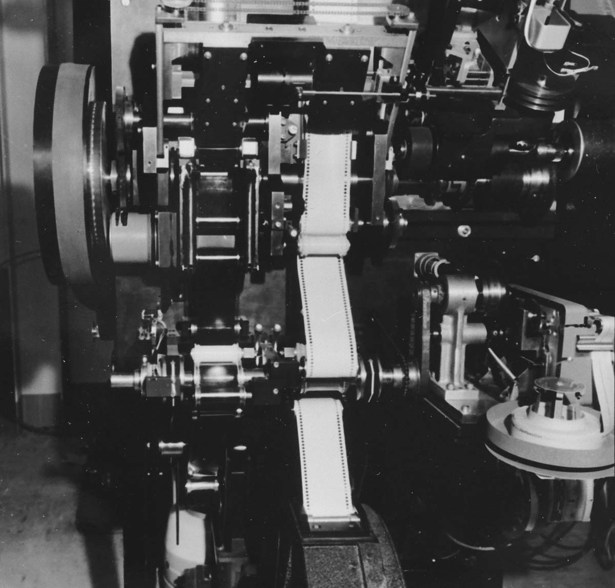
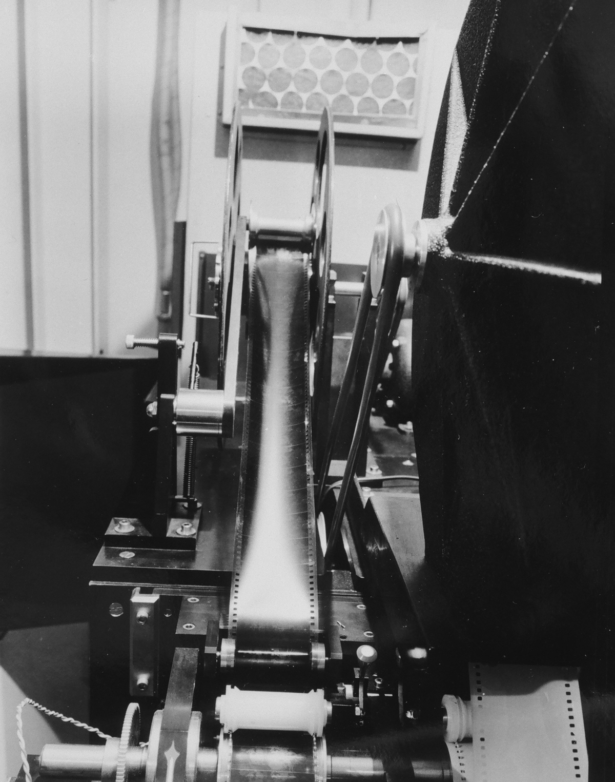 Negative
coming from the supply to the print section. Negative
coming from the supply to the print section. |
|
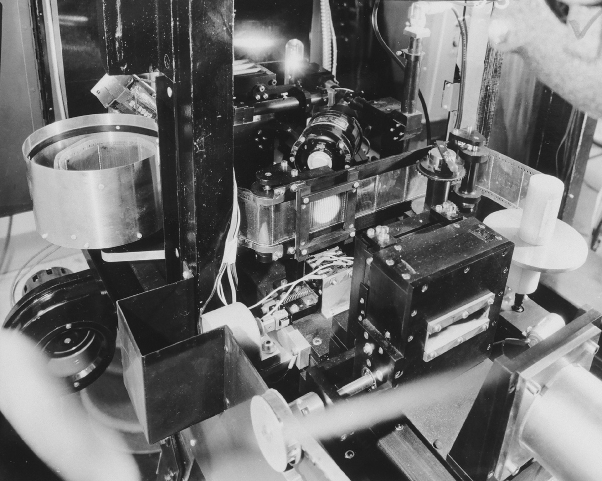
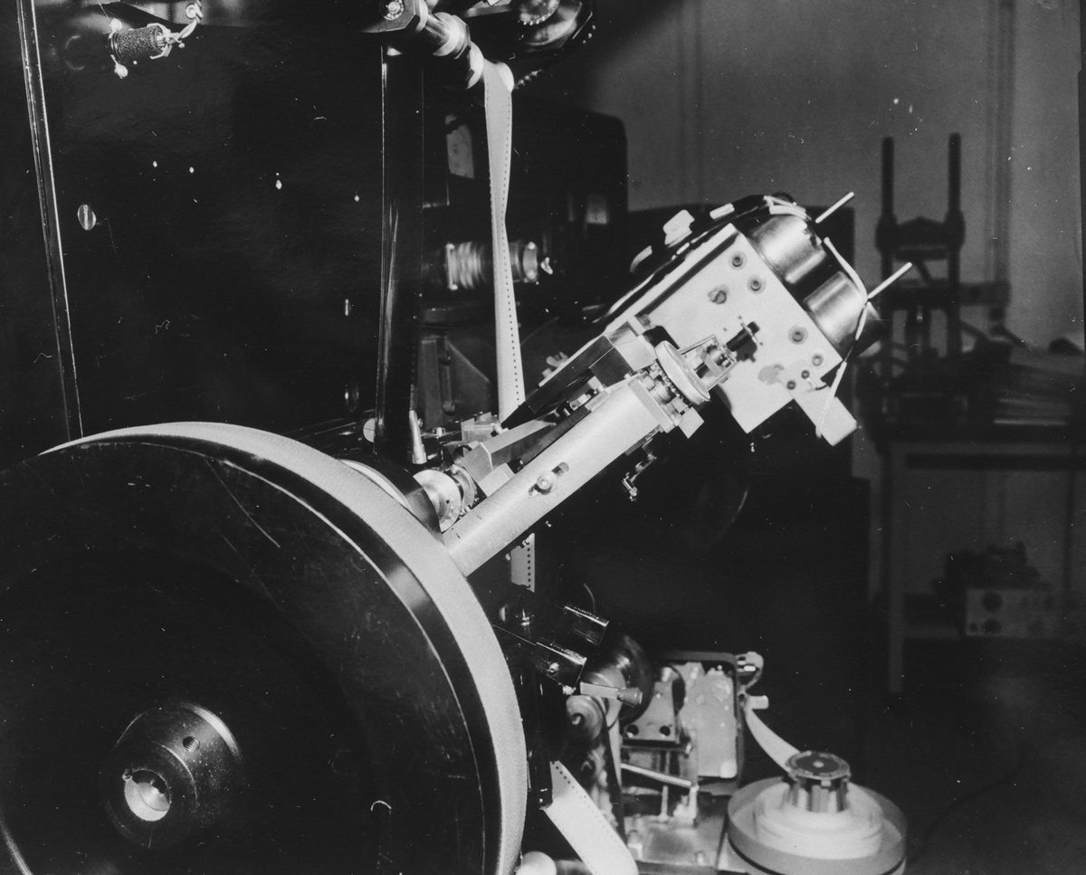
 Printing section showing on left the negative slit illuminated in
straight line & on the right the print stock on the curved shoe & slit
illuminated with a curved line (The B, or “Droop” correction). Printing section showing on left the negative slit illuminated in
straight line & on the right the print stock on the curved shoe & slit
illuminated with a curved line (The B, or “Droop” correction). |
|
 Another
front view of printing section. Another
front view of printing section.Printing section showing on left the negative slit illuminated in straight line & on the right the print stock on the curved shoe & slit illuminated with a curved line (The B, or “Droop” correction). |
|
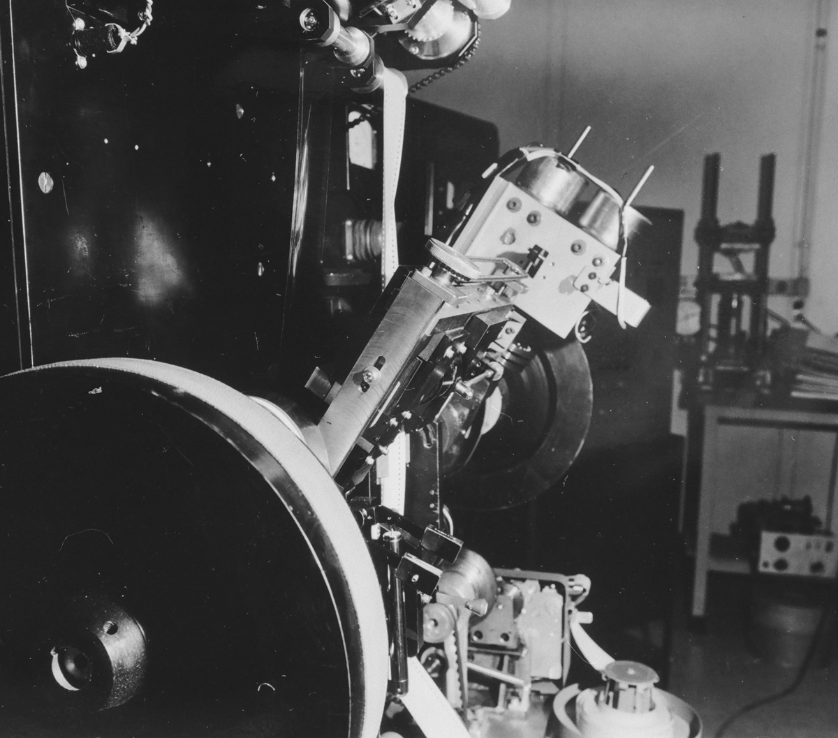
 Front view of printer showing
the correcting cam shift mechanism. Front view of printer showing
the correcting cam shift mechanism. |
|
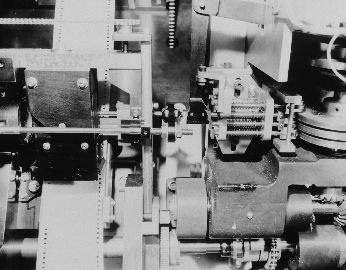 Close-up of cam shift mechanism and magnetic fluid break. Close-up of cam shift mechanism and magnetic fluid break. |
|
 Front of print section with only raw stock loaded. Front of print section with only raw stock loaded. |
|
 Front of take-up section. Front of take-up section.
|
|
 Frame line shutter top make the competition think it was a step printer. Frame line shutter top make the competition think it was a step printer. |
|
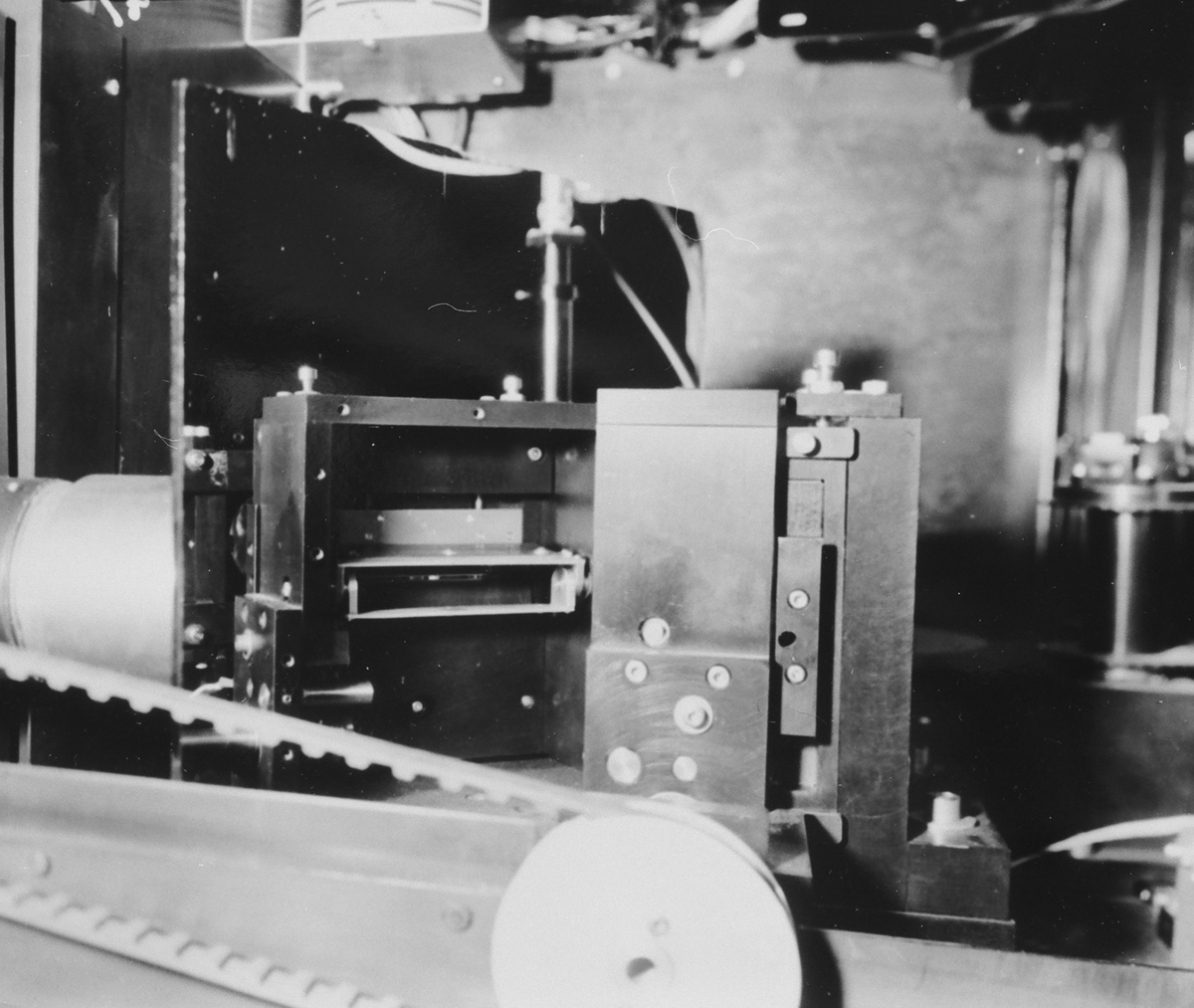
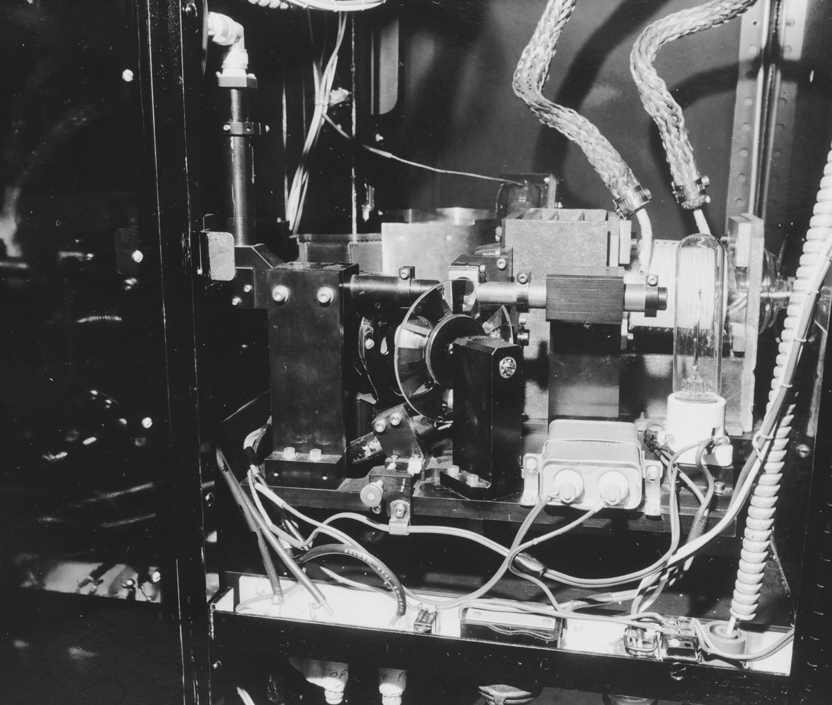
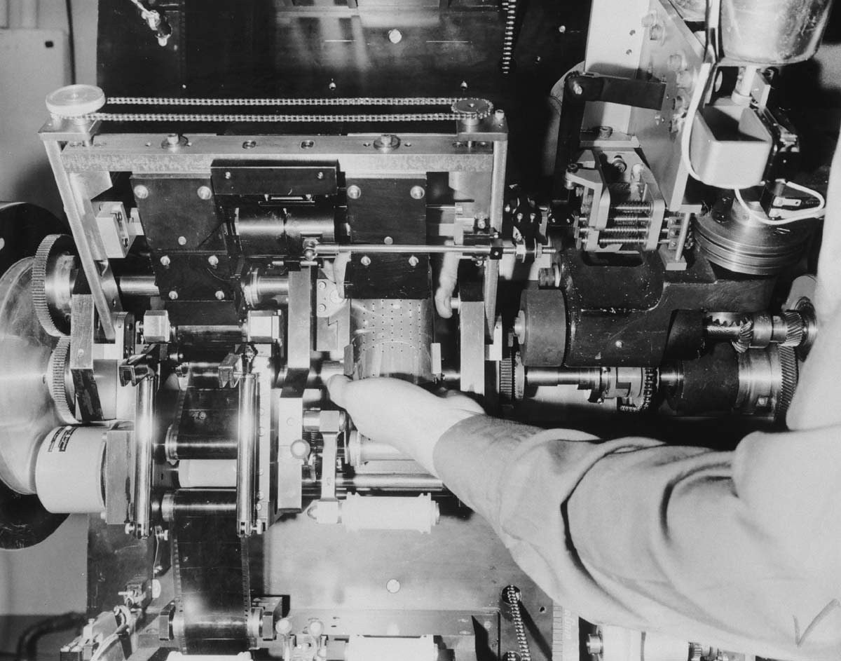 Print section from above with hand on the curved print shoe. Print section from above with hand on the curved print shoe. |
|
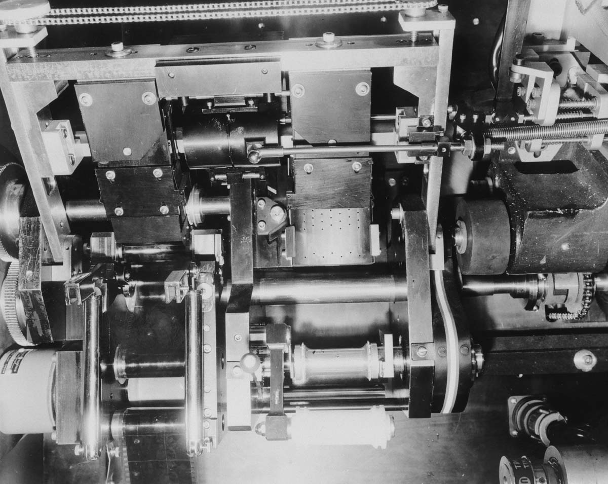 Close-up of print section. Close-up of print section. |
|
Color correcting (“timing”) filters |
|
 Color correcting (“timing”) filters for each scene were carried in
pockets on 65mm clear stock. Roll of these is contained in the cylindrical
can on left. The active one is in the circular light beam at the center.
These filters get indexed along at each scene change. Color correcting (“timing”) filters for each scene were carried in
pockets on 65mm clear stock. Roll of these is contained in the cylindrical
can on left. The active one is in the circular light beam at the center.
These filters get indexed along at each scene change. |
|
 Timing filters in their pocket carrier. Timing filters in their pocket carrier. |
|
 65mm and 35mm film reels. 65mm and 35mm film reels. |
|
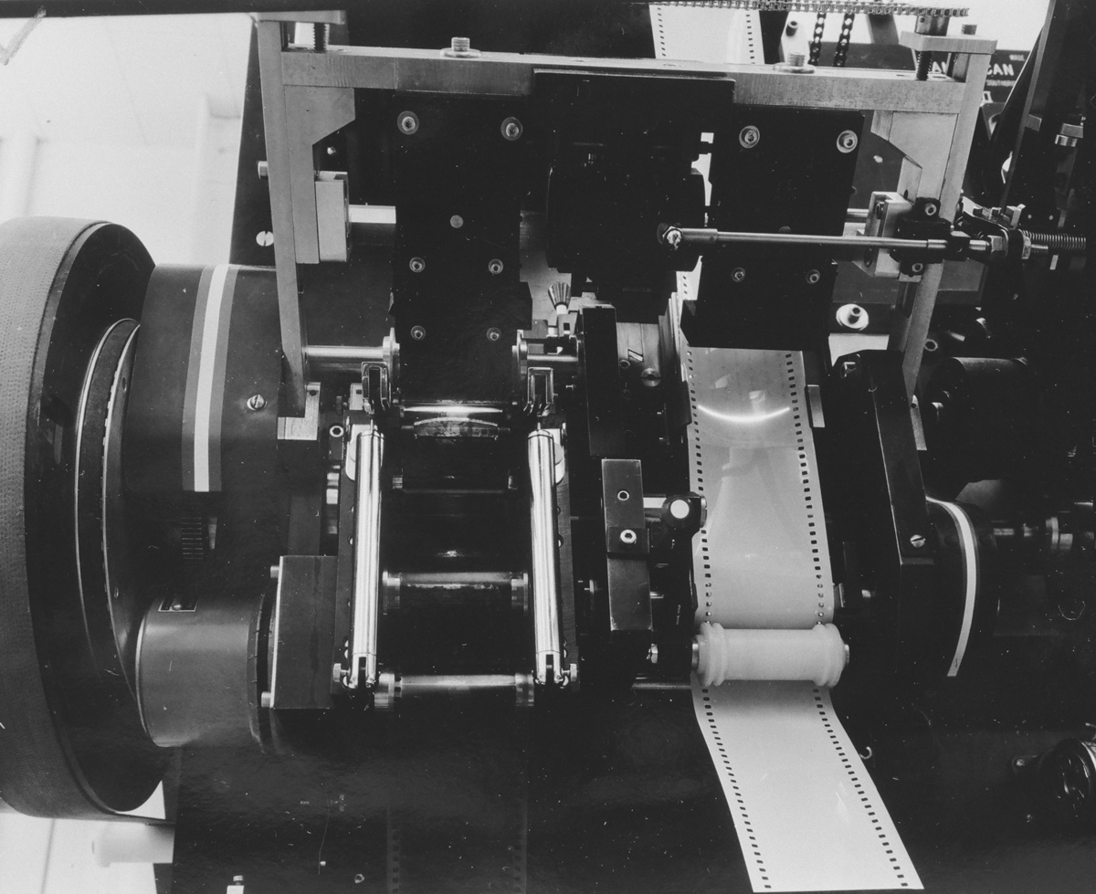
Paper Tape Reader |
|
 The printers were controlled by punched paper tape,
executing correction cam changes and filter changes at each scene change. The printers were controlled by punched paper tape,
executing correction cam changes and filter changes at each scene change.Front view showing the paper tape reader in lower right. |
|
 Front of take-up section showing the paper tape control reader on the
right. Front of take-up section showing the paper tape control reader on the
right. |
|
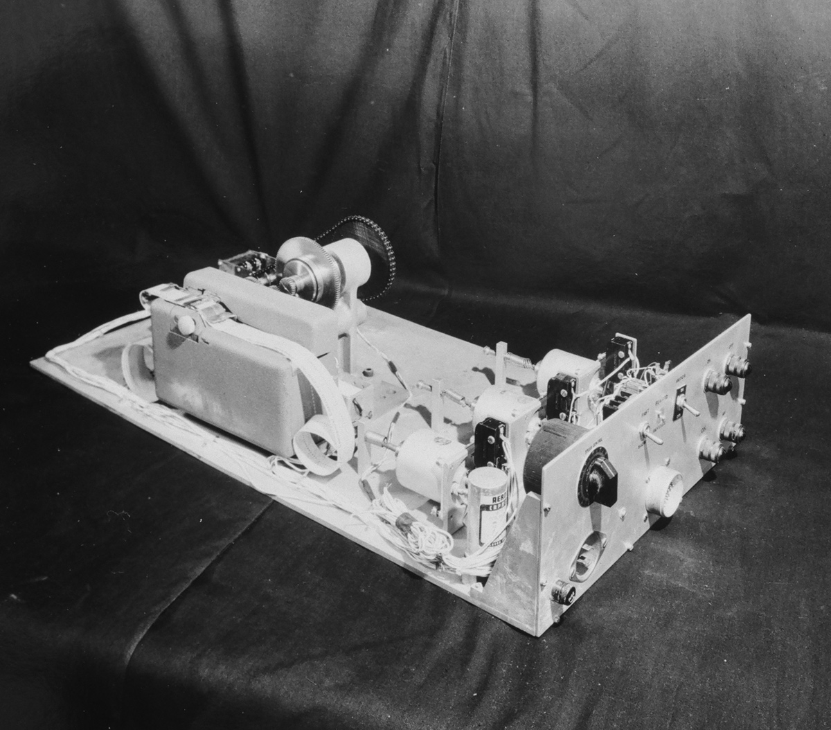
 Paper tape drive with its control. Paper tape drive with its control. |
|
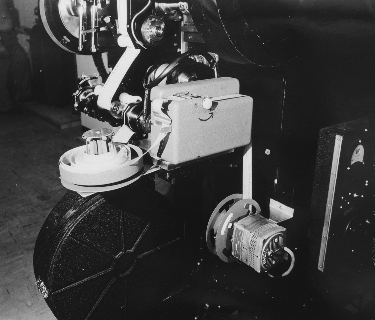 Paper tape drive on the printer. Paper tape drive on the printer. |
|
 Paper tape drive controlling scene changes. Paper tape drive controlling scene changes. |
|
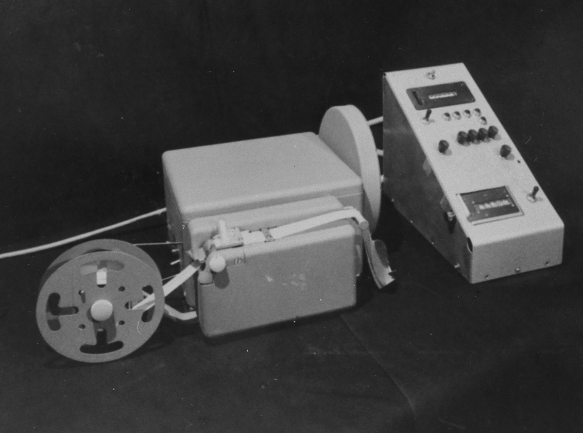
 A control unit. A control unit. |
|
 Paper
tape reel & case. Paper
tape reel & case. |
|
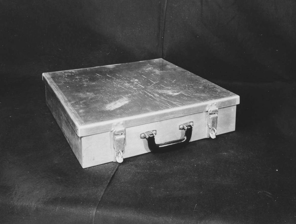 Control
paper tape transport case. Control
paper tape transport case. |
|
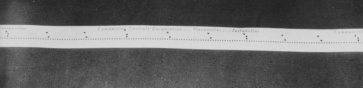 Control paper tape. Control paper tape. |
|
Printing illumination section |
|
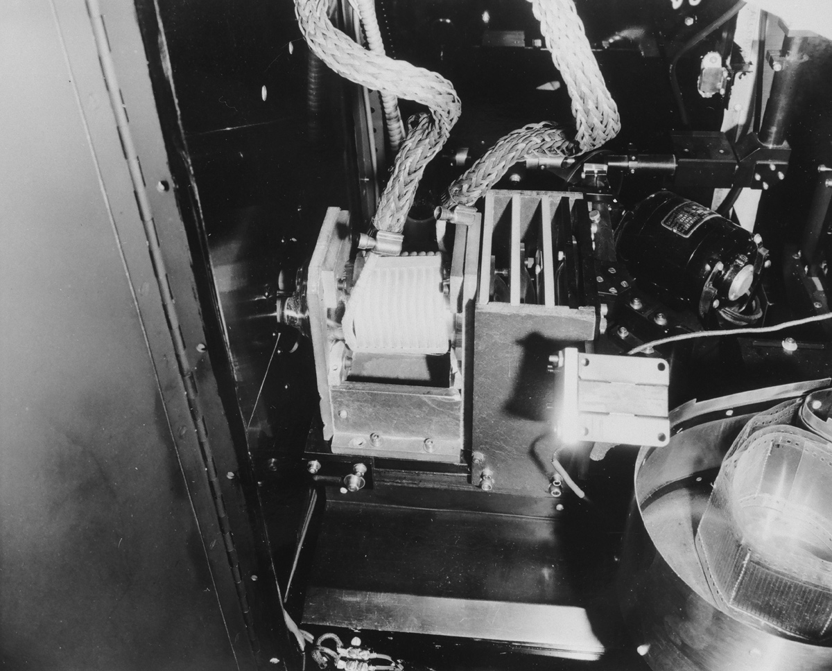 Printing
light source system. Printing
light source system. |
|
 Printing illumination section. Printing illumination section.Rear view of frame line shutter |
|
 Light source control box. Light source control box. |
|
Optical Bridge |
|
 Side view of print section with optical bridge at high droop angle. Side view of print section with optical bridge at high droop angle. |
|
 Side view of print section with optical bridge at medium droop angle. Side view of print section with optical bridge at medium droop angle. |
|
 Side view of print section with optical bridge at zero droop angle. Side view of print section with optical bridge at zero droop angle. |
|
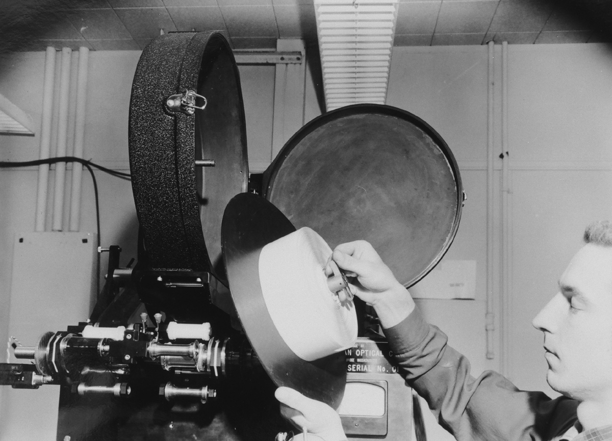
 Benny Grinsewitz focusing the optical system. Benny Grinsewitz focusing the optical system. |
|
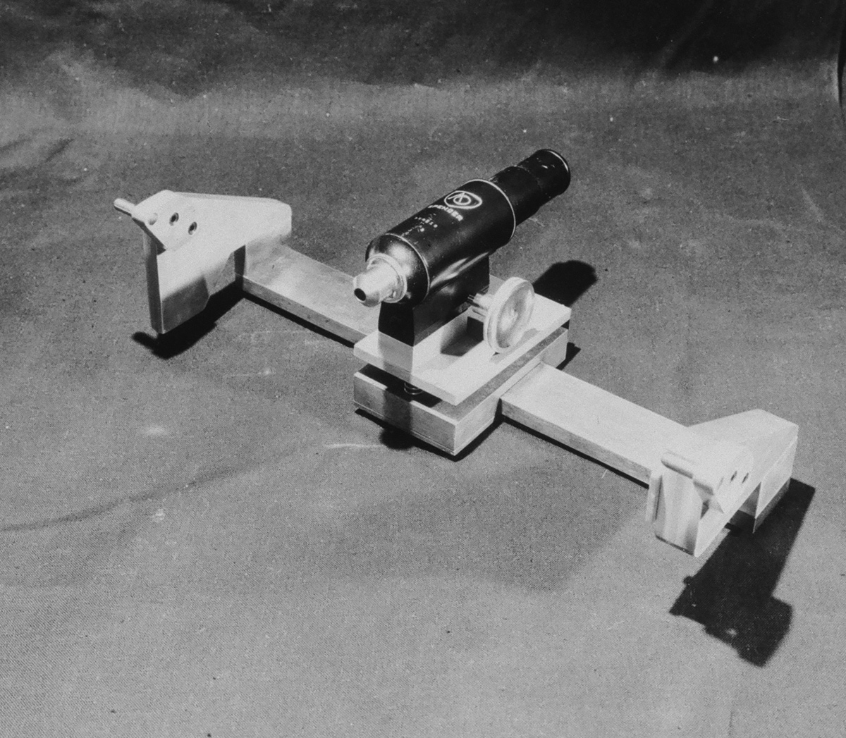 Bridge with microscope for focusing printer. Bridge with microscope for focusing printer. |
|
| Go: back - top - back issues - news index Updated 21-01-24 |